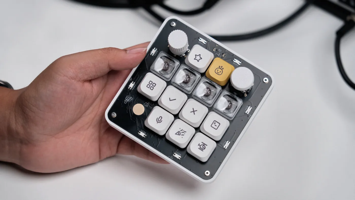
- Device
- 13-key macropad, encoder, joystick, touch pad, 21× RGB
- MCU
- STM32F072CBT6 (Cortex-M0)
- Board
- 95 × 95 mm, 4-layer
- Schematic
- 823 lines of CoHDL in 4 files
- Layout
- Quilter.ai, from compiler constraints
- License
- MIT — github.com/conol-ai/openmicrokbd
Why this board
CoHDL needed to be proven on something real with awkward requirements — not a blinky. A key matrix with per-key diodes, a rotary encoder, an analog joystick, a capacitive touch electrode drawn in PCB copper, two independent WS2812 LED chains sharing a USB power budget, ESD protection, an LDO, and a debug socket. Small enough to finish; complicated enough to be a fair test. The full story of the device — firmware, companion app, enclosure — is told in the project's own launch post. This page is about the part CoHDL played.
The schematic is 823 lines of text
The whole electrical design lives in four files under
hw/v1/src/:
the top-level design, the datasheet-verified part bindings, and the board's
footprints and pads. Thirteen switches and thirteen matrix diodes are two
declarations, not twenty-six placed symbols:
inst sw: [SW_KEY; 13]
inst d: [diode::D_1N4148W; 13]

// key matrix: rows drive, columns read through the diodes
net ROW1: mcu.PA10, sw[2..=5].A
net COL1: mcu.PB5, d[0, 3, 7, 10].Cathode
Nets carry types, not just names. The 3.3 V rail is annotated
[3.3V], so connecting a part whose supply pin can't take that
voltage is a compile error — and design intent rides along as a checked
attribute instead of a comment that quietly goes stale:
#[intent("AP2112K enable tied to VIN — always on when USB is present")]
#[high_current(500mA)]
net V3V3 [3.3V]: ldo.VOUT, mcu.VDD, mcu.VDDA, mcu.VBAT, mcu.VDDIO2,
                 joy.X_END_B, joy.Y_END_B, c_vdda.A, c_vdd_a.A, c_vdd_b.A, c_vdda_hf.A
The compiler's job is to refuse the silent mistakes. Every pin on every
device carries a connection obligation — a required pin left floating is an
error naming that pin, and deliberately unconnected pins must be declared
with nc, with a reason. Units never coerce. And because the
language is text, the diff for "swap the CC pulldowns" is two lines in a code
review, not a spot-the-difference between two screenshots.
Attributes the layout tools can consume
The design declares physics, not just connectivity. The crystal declares its oscillator region; every bypass capacitor declares which pin it serves and at what value:
#[crystal_oscillator(mcu, PF0, PF1)]
inst xtal: osc::XTAL_8M

#[bypass(mcu.VDD, 100nF)]
inst c_vdd_a: passive::C_100n_16V_X7R_0402
#[bypass(mcu.VDD, 100nF)]
inst c_vdd_b: passive::C_100n_16V_X7R_0402
Those attributes aren't decoration — they're the interface to the autorouter.
The bypass capacitors deliberately carry no hand placement:
the #[bypass] attribute is exactly what the auto-placer
consumes, so it puts each capacitor where its pin's fanout actually lands
rather than where a human guessed before any routing existed. Parts whose
positions are mechanical facts — switches on the 19.05 mm key grid, the
encoder, the USB connector — are pinned explicitly, down to which side of the
board they sit on:
place mcu at (-40mm, 24mm) rotate 270 side bottom
place enc at (-35.575mm, -31.075mm)
place sw[0] at (-9.525mm, -28.575mm)
From cohdl build to a routed board
One build emits everything downstream of the schematic: the KiCad netlist,
the BOM, a .kicad_mod per footprint, the layout-constraint
document, an IPC-2581 handoff file, and the physics-hint CSVs the autorouter
reads. All of it is checked into the repository under
hw/v1/out/,
and all of it is deterministic — rebuilding the same source produces the same
bytes.
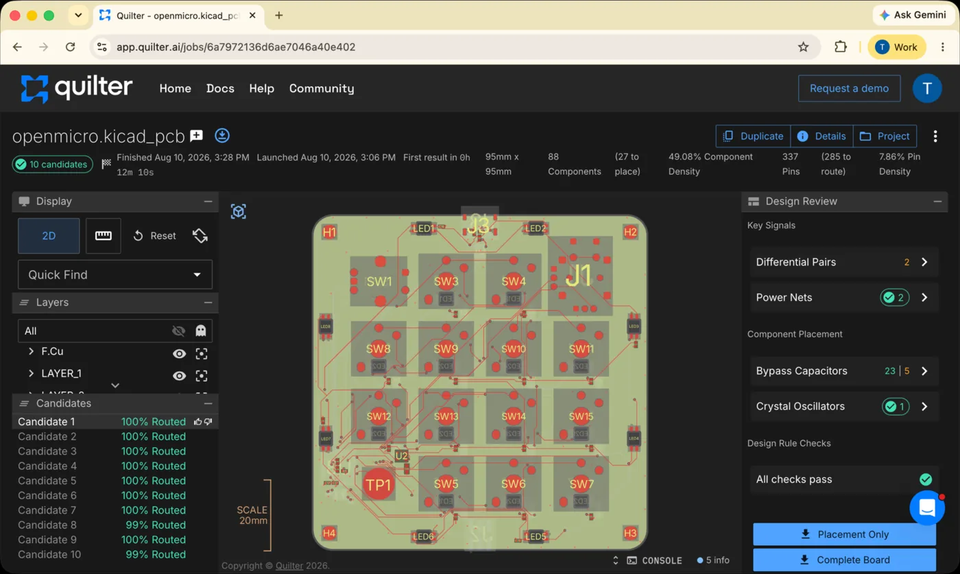
Physical layout is Quilter's work, not CoHDL's — the routing is not written by hand or by the compiler. Quilter took the netlist, the locked placements and the physics hints, and placed and routed 88 components and 337 pins, returning ten candidate boards in about twelve minutes.
One source of truth, firmware included
The firmware's pin map is generated from the hardware source, which removes a classic two-file failure: changing a schematic pin and forgetting the firmware constant that mirrors it. Generated files aren't automatically correct — they preserve bad choices as faithfully as good ones — but electrical intent and firmware assumptions can no longer silently drift apart.
Version 2 is the same language on a radio
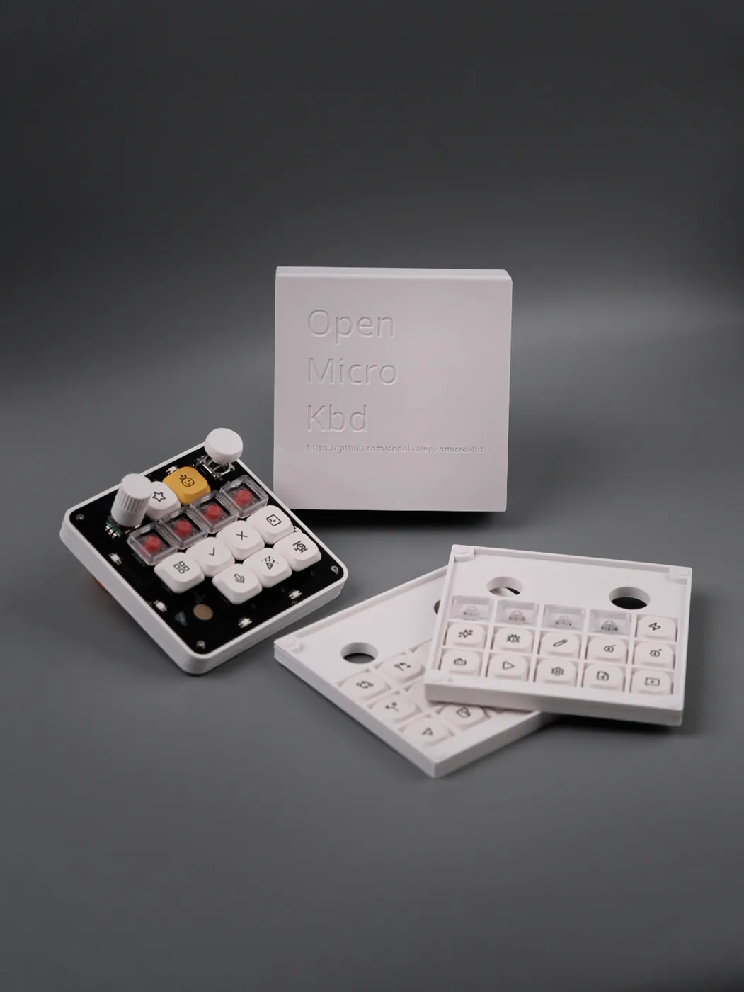
The wireless successor is already written: hardware v2 moves to the SiFli SF32LB52 — BLE, battery-powered — and lives beside v1 in the same repository as CoHDL source with compiler outputs, not yet routed. Same language, same pipeline, different physics. That's the point of the schematic being a program: v2 is a revision you can read as a diff, not a new drawing.
Honest boundaries
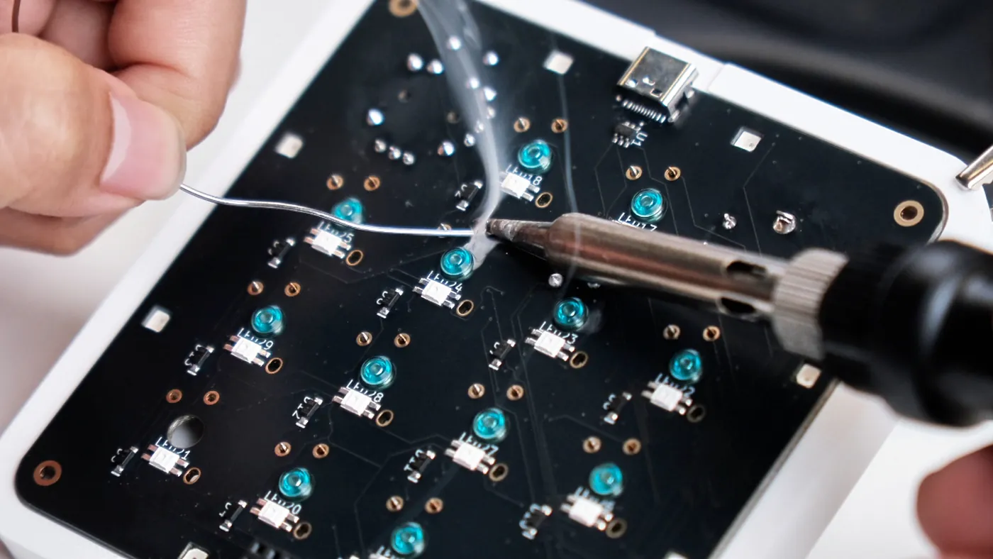
- CoHDL produced the schematic, its checks, and the generated outputs. Placement and routing are Quilter's work; hand review, soldering and bring-up were human work throughout.
-
Source hardware is most useful when anyone can run the whole toolchain —
and now anyone can: the compiler is
open source with a
one-line installer, so
hw/v1/src/rebuilds on your machine. The complete compiler outputs are also checked into the repository, so every generated artifact is inspectable without installing anything.